NEMA Wiring Diagram Guide for Electrical Experts
Approximately seventy percent of the electrical failures in installations result from inadequate wiring methods. This fact accentuates the necessity of following recognized guidelines, spotlighting NEMA wiring diagrams’ importance for electrical experts. Via these drawings, wiring setups that meet both performance productivity and highest security criteria are delineated.
The purpose of this document is to provide electrical practitioners with deep understanding into NEMA standards. Emphasizing the significance of proper electrical installations is crucial. By learning these rules, practitioners can significantly minimize the likelihood of hazards and confirm they comply with safety standards backed by Installation Parts Supply. Expertise in NEMA l14-30R wiring diagram is essential whether designing modern networks or repairing current ones, as it enhances the capacity to provide reliable and consistent electrical answers.
Summary Highlights
- NEMA wiring schematics are vital for guaranteeing electrical protection and compliance.
- Correct wiring practices can minimize electrical malfunctions considerably.
- Comprehending NEMA standards enhances the performance of electrical setups.
- Installation Parts Supply supports compliance with safety protocols in electrical work.
- NEMA diagrams accommodate a wide range of applications across different sectors.
Grasping NEMA Criteria and Their Significance
NEMA norms are crucial in the electrical sector, steering safety and operation meticulously. Crafted by the National Electrical Manufacturers Association, they define pivotal criteria for developing, examining, and labeling electrical equipment. This ensures standardization and dependability across all electrical set-ups, which is of great value.
What Are NEMA Norms?
NEMA categories span from classes 1 up to 13. Every level specifies the parameters required for electrical devices to function efficiently. For example, NEMA 1 provides fundamental indoor security but does not offer dust resistance. Alternatively, NEMA 4 guarantees devices is watertight, a necessity for surviving significant water exposure. Grasping these categories is key in picking appropriate appliances.
Why NEMA Criteria Are Important for Electrical Protection
The role of NEMA norms in guaranteeing electrical security is profound. They contribute greatly in minimizing electric shock, equipment failures, and fire hazards. Proper adherence to NEMA standards enables devices to perform reliably under particular ambient conditions. For outdoor deployment, NEMA 3 ratings provide protection against the elements, shielding the device from harsh climate like precipitation and snow. In regions prone to explosions, standards including NEMA 7, 8, and 9 are vital for ensuring safety.
Applications of NEMA Standards in Wiring Diagrams
The application of NEMA norms in wiring schematics is vital for protected, optimal electrical installations. These diagrams make use of uniform symbols and structures derived from NEMA standards, simplifying the comprehension of complex electrical configurations. This uniformity is advantageous. It promotes lucidity, standardization, and minimizes errors, and thereby boosting electrical safety across residential and industrial environments.
NEMA Wiring Diagram Fundamentals
NEMA wiring diagrams are crucial for electrical professionals, making intricate junctions unambiguous. They describe the connections and parts in different configurations. By grasping the components, kinds, and symbols of NEMA diagrams, electricians can improve their operations in installations and servicing.
Elements of NEMA Wiring Schematics
NEMA drawings comprise essential parts for distinct electrical setups. You’ll see wiring connection points, couplers, and various equipment for secure connections. Each piece guarantees power is spread effectively, complying with security standards.
Categories of NEMA Wiring Schematics
NEMA uses multiple drawings, like linkage blueprints and circuit layouts. These schematics detail equipment interconnections, while designs display energy distribution. Selecting the correct drawing helps with problem solving and deployment.
Typical Symbols Employed in NEMA Wiring Drawings
Notations in wiring schematics are vital for unambiguous clarity. They depict toggles, loops, and couplers. Understanding these symbols aids groups interpret drawings accurately. Such practice ensures configurations comply with NEMA standards.
NEMA Wiring Schematic Features
For electrical professionals, understanding the core aspects of precise electrical wiring diagrams is vital. These drawings provide both lucidity and wholeness, synchronizing installations with NEMA criteria. They necessitate accurate labeling and proportioning to reduce deployment issues. Such practices promote a more secure and more efficient working environment.
Essential Attributes of Correct Electrical Wiring Drawings
Correct electrical wiring drawings are vital in electrical undertakings. They encompass crucial attributes such as:
- Clarity: Diagrams are required to be unambiguous, minimizing misinterpretation risks.
- Thoroughness: They must include all key parts, connections, and electrical standards.
- Adherence to Standards: Following NEMA criteria is non-negotiable for ensuring security and functionality.
- Comprehensive Marking: Distinct annotations on each element are crucial for grasping and error prevention.
- Proper Sizing: The proportions should reflect the actual setup to portray the system precisely.
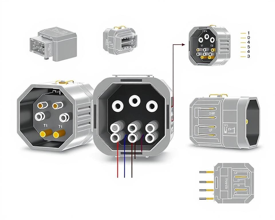
Understanding NEMA Coupler Pinout
Understanding of NEMA connector pinout is critical for forming accurate linkages in electrical setups. Awareness of particular pin configurations maintains safety and appliance operation. There are a diversity of NEMA connectors, intended for specific power levels and currents, covering:
| NEMA Connector Type | Ampere Rating | Power Rating |
|---|---|---|
| L5-15 | 15A | 125V |
| L5-20 | 20A | 125V |
| L14-20 | 20A | 125/250V |
| L1430C | 30A | 125/250V |
| L620C | 20A | 250V |
| L1430C | 30A | 125/250V |
| L630R | 30A | 250V |
Grasping NEMA connector configurations is essential for secure junctions, improving efficiency. It’s paramount to match couplers with devices properly using twist-lock or straight blade variants, to prevent hazards.
NEMA Appliance Wiring
NEMA appliance wiring encompasses multiple arrangements for secure electrical device interfaces. These rules confirm that equipment work together securely, lowering hazard. Knowing the various NEMA equipment and their wiring is vital for technicians.
Various Types of NEMA Units
NEMA organizes units by type based on power levels and amperage needs. Primary setups are:
- 2-Pole, 2-Wire
- 2-Pole 3-Wire Grounding
- 3-Pole, 3-Wire
- 3-Pole 4-Wire Grounding
- 4-Pole 4-Wire
- 4-Pole 5-Wire Grounding
These arrangements find use in residences and factories, handling 125V, 208V, and 480V.
NEMA Plug Wiring Outlined
NEMA plug wiring changes to meet diverse electrical demands, with twist-lock types providing reliable junctions in vibrating environments. For example, the L5-15 plug operates at 15 amps, typical of commercial locations, whereas the L14-20 is intended for 20 amps at 125/250 volts.
The NEMA designation system helps in choosing the correct plugs, spotlighting characteristics like electrical polarity and connection to ground. This meticulousness ensures that devices perform reliably.
NEMA Receptacle Wiring Guidelines
Proper wiring of NEMA outlets aligns with electrical standards and safety guidelines. For example, L530R receptacles are configured for 30 amperes at 125 volts, with L630R models for 250 volts. Correct grounding is crucial to dodge electrical mishaps.
Selecting approved NEMA plugs and receptacles secures protected, regulation-compliant installations. It’s critical to refer to authoritative protocols when implementing.
NEMA Motor Wiring and Applications
NEMA motor wiring is crucial in electrical engineering, especially for manufacturing use. Knowing how NEMA motor arrangement works secures that machines are set up for optimal efficiency. Such devices, like single-phase and tri-phase variants, need correct wiring to function reliably and efficiently.
Overview of NEMA Motor Wiring
Understanding NEMA motor wiring necessitates knowledge of connections and setups. The majority of three-phase motors are compatible with dual-voltage, meaning they can operate at both low (208-230V) and high voltage levels (460V). Wiring at high voltage makes a motor use less current than at low voltage. High voltage perks include smaller wires for the power feed, a significant benefit for units exceeding 10 HP.
While both NEMA and IEC appliances are used in the market, NEMA versions are generally larger and more expensive than IEC ones for less than 100 HP deployments. NEMA starters span size 00 to 9, fit for diverse functions. A standard feature in NEMA controllers is a Trip Rating of 20, designed to trip when a motor’s amperage goes beyond 6-fold the rated current in 10 secs.
Selecting the Correct NEMA Motor Setup
Choosing the right NEMA motor configuration affects overall performance and safety. A common three-wire control circuit employs three wires for a power control pushbutton station, allowing direct motor operation. Frequent three-phase setups consist of the 12 Lead Dual Voltage and 6 Lead, facilitating Wye and Delta arrangements.
IEC motor starters commonly feature phase loss detection, boosting safety. They also feature modifiable Trip Classes for customized protection in low voltage levels operations. Moreover, many units have thermal protection, vital for single-phase and Dual Voltage setups.
| Arrangement | Voltage Type | Current Specification | Common Application |
|---|---|---|---|
| 12 Lead Dual Voltage | Dual Voltage (208-230V / 460V) | Varies by motor size | Applications with Wye Start and Delta Run |
| 6 Lead | Single or Dual Voltage | Up to 32 amps | Wye/Delta configurations |
| Single Phase | One Voltage | Varies (1-5 amps adjustment) | Dual Speed and Dual Winding setups |
| Delta Connection | High-Power Voltage | Based on configuration | Various applications including Current Transformers |
Final Thoughts
Grasping NEMA wiring diagrams and norms is vital for electrical professionals seeking to boost their expertise and adhere to electrical safety norms. These principles guarantee safe and efficient electrical setups but also prevent dangers stemming from improper wiring. As discussed, following NEMA norms yields the improved functionality of multiple NEMA devices and setups.
For electrical professionals, the choice of high-quality resources can profoundly influence the success of their work. Installation Parts Supply provides a vast selection of wiring items aligned with NEMA standards. This empowers experts to access vital elements for fulfilling these important standards. High-quality resources and deep expertise of NEMA wiring diagrams greatly enhance system security and effectiveness.
Throughout electrical installations, always prioritize protection and exactness first. Mastering NEMA standards delivers the insight necessary for implementing optimal procedures accurately. This ensures that each electrical connection formed aligns with premium criteria.
FAQ
What are NEMA wiring schematics?
NEMA wiring diagrams illustrate the setups and connections of NEMA-standard electrical devices. They follow safety and performance norms set by the National Electrical Manufacturers Association.
Why are NEMA norms crucial for electrical security?
NEMA criteria are fundamental to setting safety and operational standards for electrical devices. These standards enable electrical experts reduce electrocution risks, equipment failure, and burn dangers.
What components are essential in a NEMA wiring drawing?
Essential components in a NEMA wiring diagram consist of circuit setups and junction blueprints. These diagrams also feature thorough annotations and illustrate the electrical system’s various parts correctly for deployments.
What types of NEMA wiring diagrams are used?
Multiple NEMA wiring schematics serve diverse requirements, including energy distribution layouts and connector schematics. Each diagram serves a unique role in electrical installations.
Which are the typical symbols used in NEMA wiring diagrams?
Standard symbols in these schematics symbolize switches, circuit breakers, outlets, and other elements. Utilization of these symbols promotes clear interaction and precise analysis of wiring schematics.
What are the essential attributes of correct electrical wiring diagrams?
Accuracy in electrical wiring drawings is marked by their clarity, comprehensiveness, and detailed marking. They must align with NEMA norms to prevent faults in installation.
What is a NEMA connector pinout?
A NEMA connector layout describes electrical connections at a connector, displaying particular pin roles. This guarantees reliable and optimal linkages in electrical setups.
Which are the various kinds of NEMA units?
NEMA units comprise various electrical receptacles and interfaces, like connectors and receptacles. They are engineered for different amperage and voltage levels criteria to meet specific usage needs.
How is NEMA plug wiring set up?
NEMA plug wiring hinges on particular amperage and voltage levels needs, complying with safety standards and electrical codes for diverse electrical setups.
Which standards are there for NEMA receptacle wiring?
Guidelines for installing NEMA outlets emphasize adhering to electrical standards, securing proper electrical polarity, and choosing correct cable sizes. This ensures both security and operation in electrical configurations.
Describe how to wire a NEMA motor properly?
To set up a NEMA motor, one must grasp its particular single-phase or tri-phase configuration. Choosing the correct wiring method is vital, in addition to observing electrical safety for enhanced motor efficiency.
What should I consider when selecting a NEMA motor arrangement?
Opting for a NEMA motor arrangement demands an assessment of the project’s energy requirements and functional attributes. It’s also vital to verify compatibility with pre-existing equipment for guaranteed efficiency and security.